Thank you Øivind, I appreciate that, I will follow up the links later, in the meantime here are some pix of the chunk in the lathe and my rough sketches which will give you some idea of my design. It's evolving as I go so what you see may vary from the finished article.
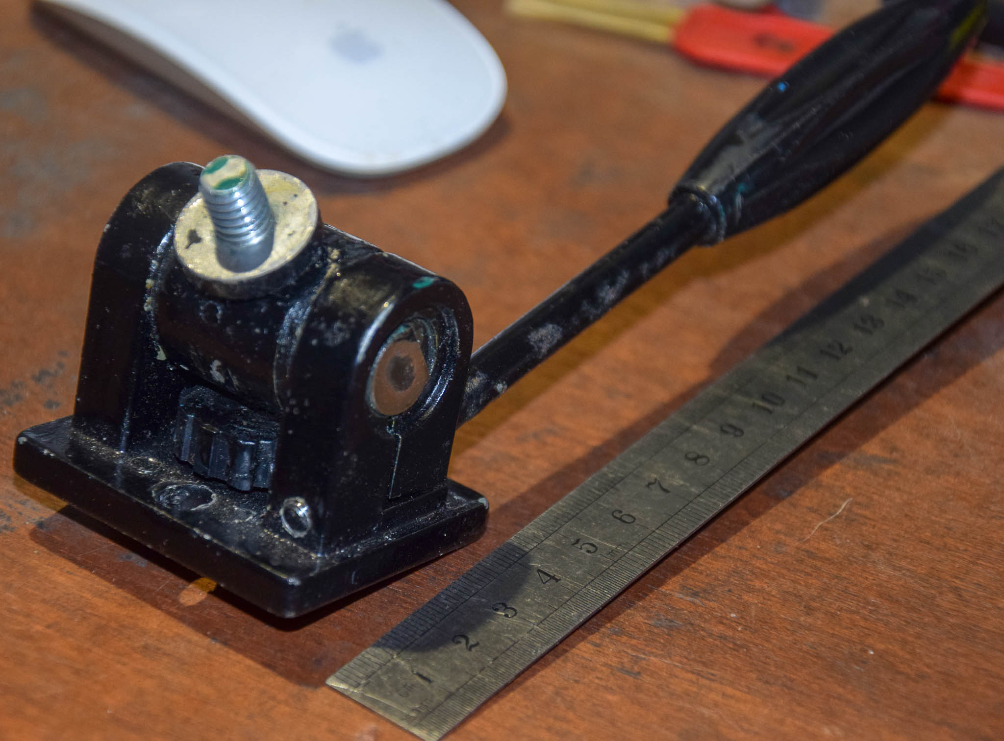
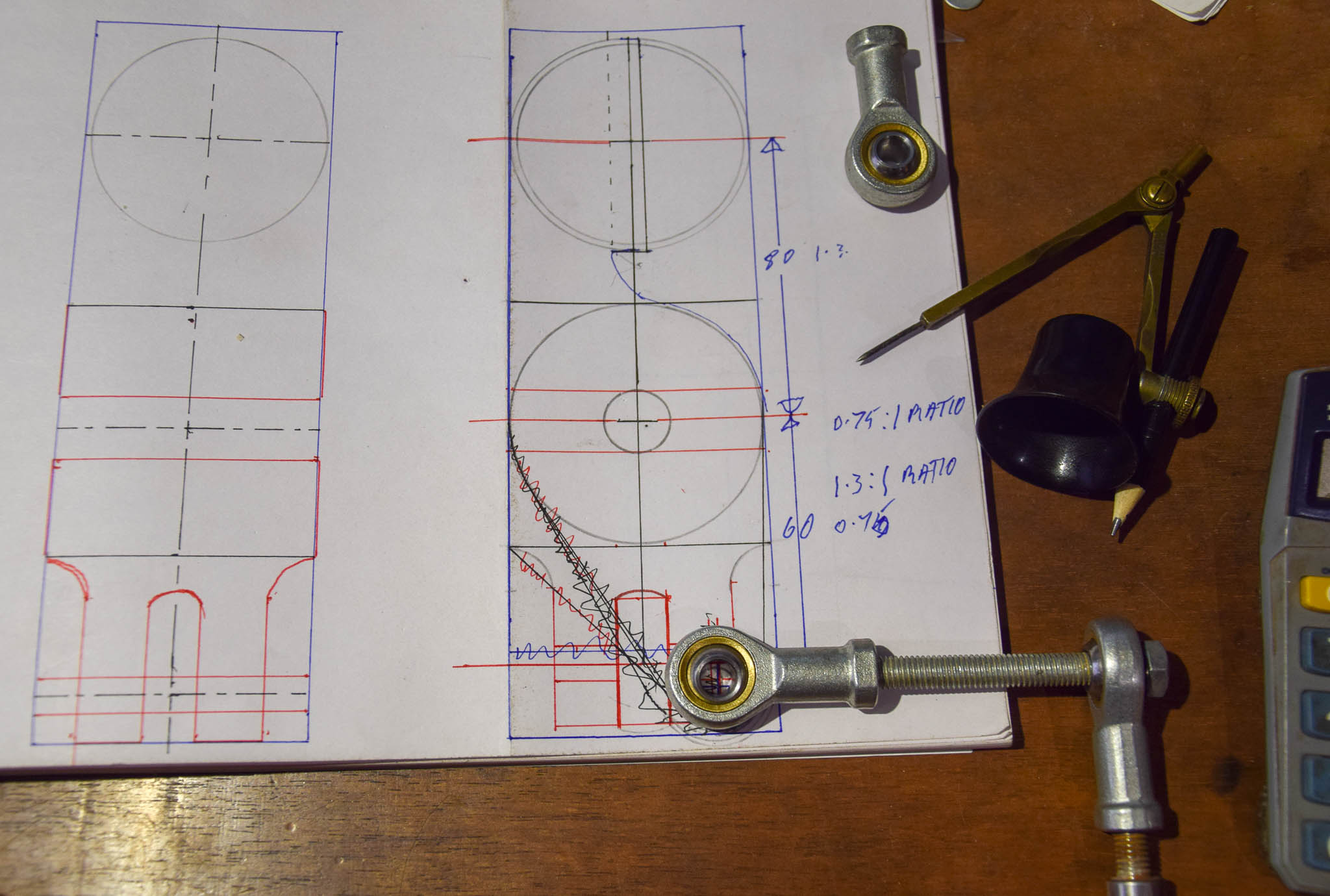
The first pix are two of my drawings. I am completely remaking the main arm which supports the Vixen gearbox/worm housing The original is a wedge base, the threads were stripped and one (badly) helicoiled. I removed the ¼" helicoil and threaded it 3/8" UNC. The previous 'wedge mount' was worse than useless as I am sure you will agree! Below...

These are my sketches, simplistically I am re-creating the bracket which bolts to the gearbox and which surrounds the polar scope, my bracket will have a pivot shaft through it where the original bracket had an angled platform to bolt to a tripod or table top.
Below the central pivot will be a clevis into which a rose joint will seat providing the required adjustment from 0º, horizontal, or just below (allowing for terrestrial setup and checking), to +60º giving some margin for the tripod to be out of kilter. I am still working on the base design, once the arm is finished I will turn my attention to the base, although of course I am hoping the arm will have avoided as many pitfalls as I can envisage.

The adjustment screws for the azimuth will turn the mount 1.4º per revolution and the altitude adjustment will raise or lower the aim by 1.25º per revolution of the adjustment screw, pretty well in line with the current Vixen base adjustments.

Here is the chunk of aluminium, 2.5" square bar, about 9" long. I am boring out the hole for the polar scope. The pivot hole and the adjustment pivot will of course be at 90º to the polar scope hole, vertical bored in the below illustration orientation. The original painted bracket is included for comparison.

One aspect of the design which is troubling me is how to lock the rotation of the altitude adjustment axis very positively without causing marks on shafts or machined faces. I am considering having the main pivot slightly loose axially and embedding a bicycle brake disk pad in either side of the trunnion side brackets, which can be clamped with a lever, a bit like a bicycle brake disk. I want the brake to have zero effect on the altitude or azimuth settings, delicate as they are.
The azimuth adjustment will be in the base with two opposing adjustment screws operating on a dovetail stop, which will have dual duty of adjusting the azimuth and tending to clamp the rotating section to the stationary platform on top of the tripod. All of which I am trying to keep as compact and low profile as possible, while allowing for essential freedom and 'elbow room' for the movements of the mount. I may also embed two small brake disk pads in the interface between the azimuth rotating part of the base and the bottom (tripod head) plate to prevent movement and stabilise the assembly.